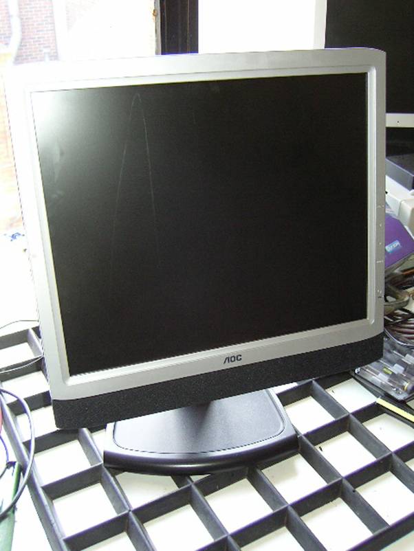
Fixing the AOC LM727
This fixes the screen going blank after so many seconds. The green light remains on but the screen is dark.
It is usually a dry joint on one of the coils. Anything else is more complicated
and it is suggested you consult the manual for such things. A buubling capacitor can cause a similar fault on these monitors.
Please do not even begin to try this if you are not good with
electronics, soldering or you are just generally a loser. Electrics are
dangerous. Please make sure you know what you are doing.
The following instructions are aimed at those who can follow instructions and solder in a decent manner. If you can’t solder, go away and learn before attempting something serious like this.
For everyone else, this shouldn’t take you too long. The longest part is getting the thing apart.
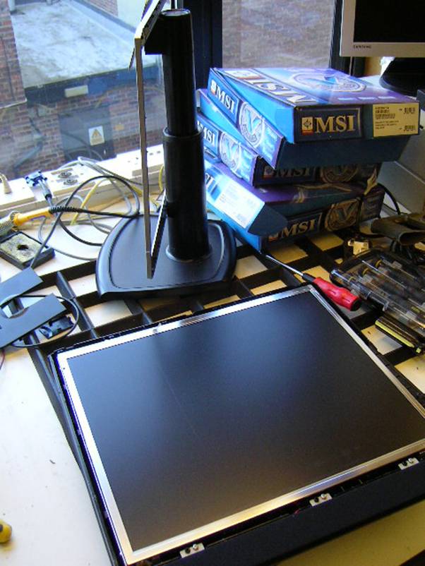
First, plug your soldering iron in and let it warm up whilst you take the monitor apart.
Lay the monitor screen facing down on something soft (we don’t want a knackered screen)
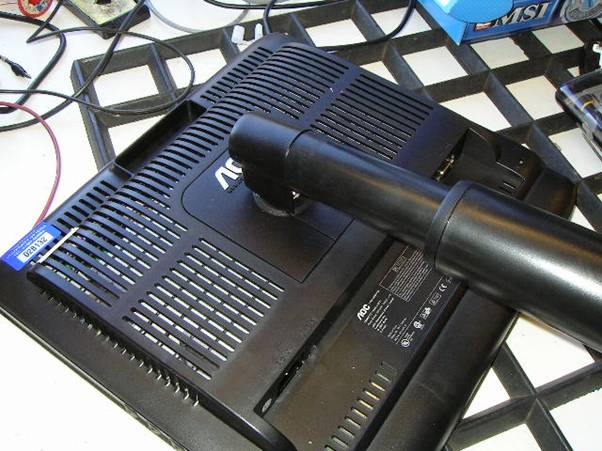
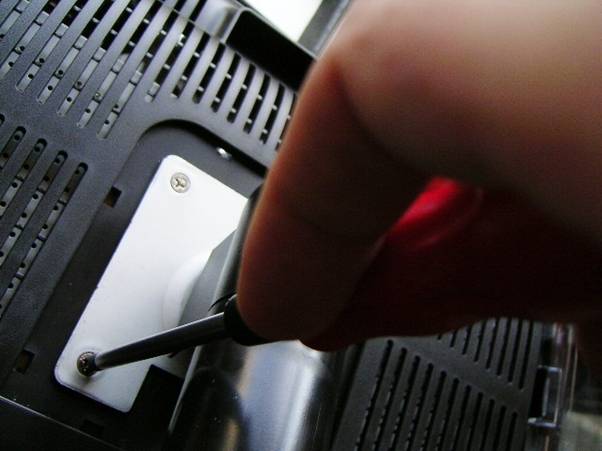
Pull the back plate off using a flat head screwdriver. The extra little flap will fall off too.
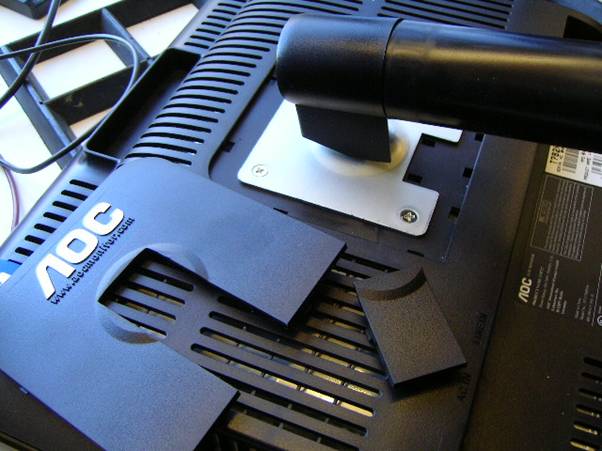
[Below] The screws (4 of them) need to be removed to take off the heavy mount. Be careful not to let it drop on your foot (or floppy bits (maybe hard bits, if you enjoy electronics so much)) after you remove the last screw.

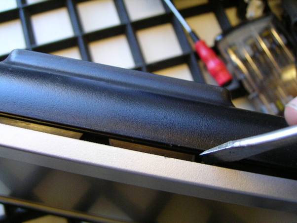
[Below] The next bit is slightly tricky without making dents in your monitor frame. Starting at the top, use a large flat head screwdriver and slowly open the frame a bit at a time. You may damage the odd lug, but after it is half open the stress on them will be relieved.
The bottom part just requires you to gently pull it away from the speaker area. Pull it up at an angle of around 45 degrees. It should clip out. You haven’t got anything to lose. It isn’t much use not working.
Next you need to unscrew the retaining screws that hold it to the plastic frame.
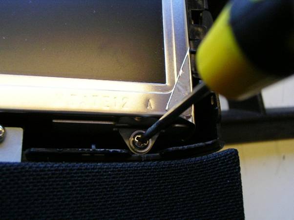
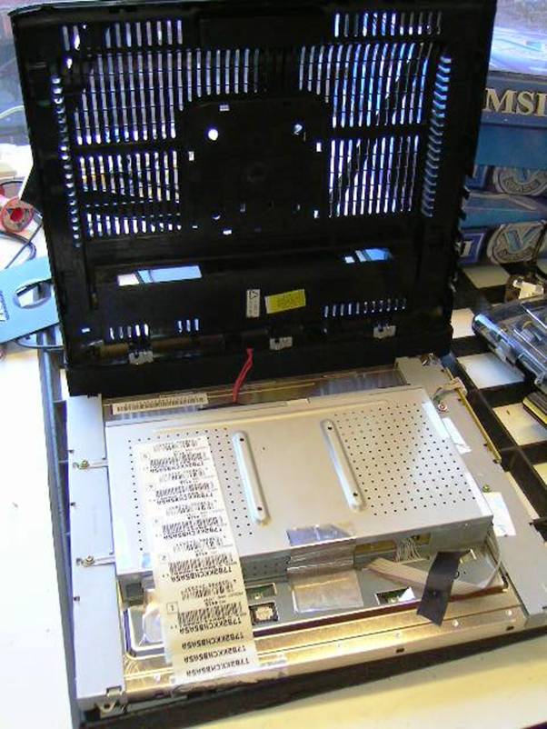
Once these are out, you can prise open the frame and the screen will come out. Be careful not to let it fall out! There is a thin cable that will remain once it is separated. This should be kept in mind. Don’t stretch or damage it. I just keep the frame propped up against the mount whilst I work on the board.
The little lugs that hold the screen in place are just plastic bendy lugs and will move with the strength of a normal little screen driver.
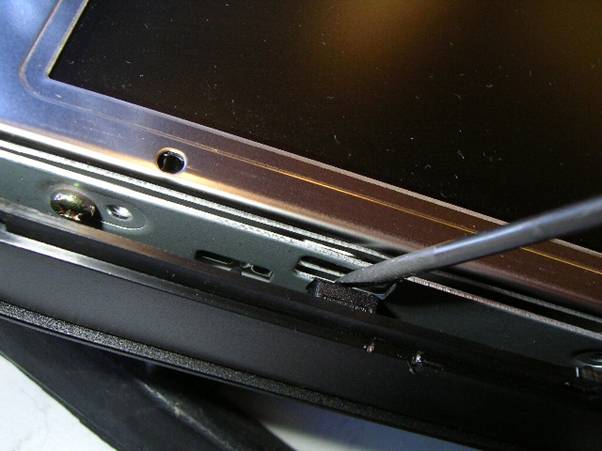
Pull the screen slightly forward as you open the lugs.
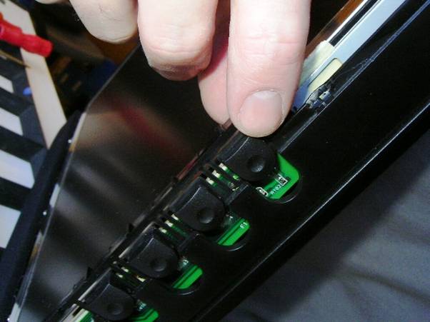
Don’t forget the buttons at the side. You can either leave them in and avoid losing them or you can remove them to save damage.
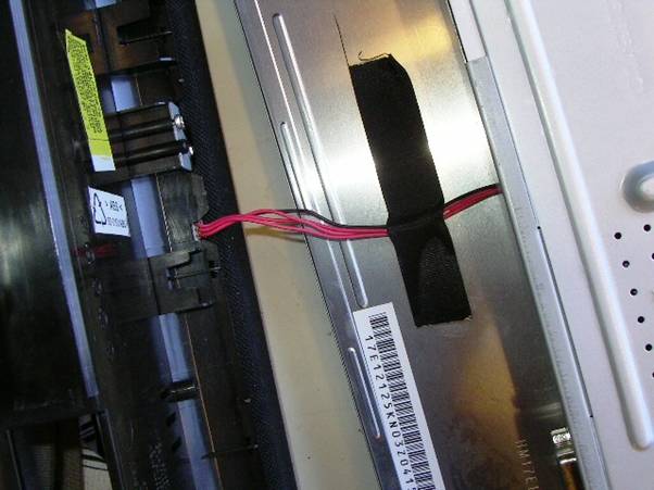
Above, you can see the cable that you don’t want to stretch too much.
Keep the screen and case near to each other, if you keep the cable plugged in.
As you can see – it can be propped up against the monitor support arm.
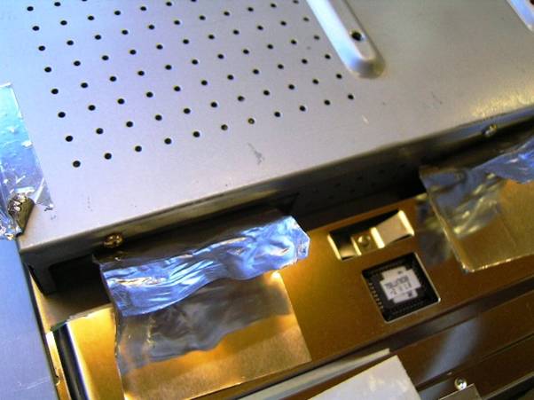
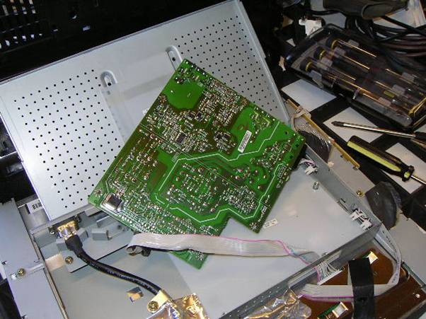
Next you have to pull back the sticky foil to remove the lid and get access to the screws.
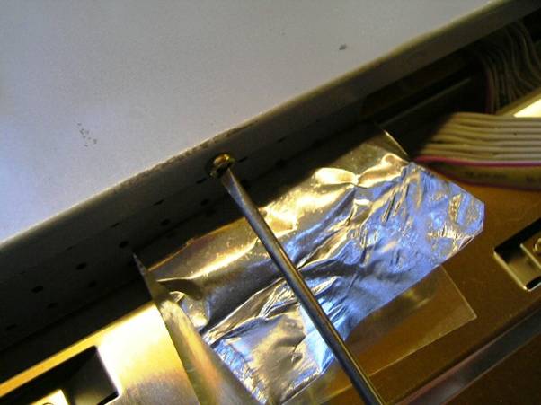
Unscrew the 3 screws and then you will have the lid off the board.
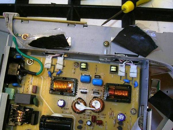
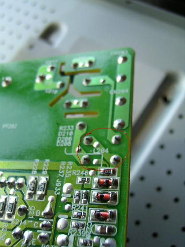
The area you are looking at in the picture is pretty much the area where the fault will be. It is a dry joint usually.
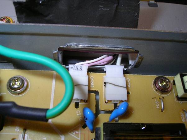
You must make a note of the colour coding of these connectors, as you need to remove them to lever the board out.
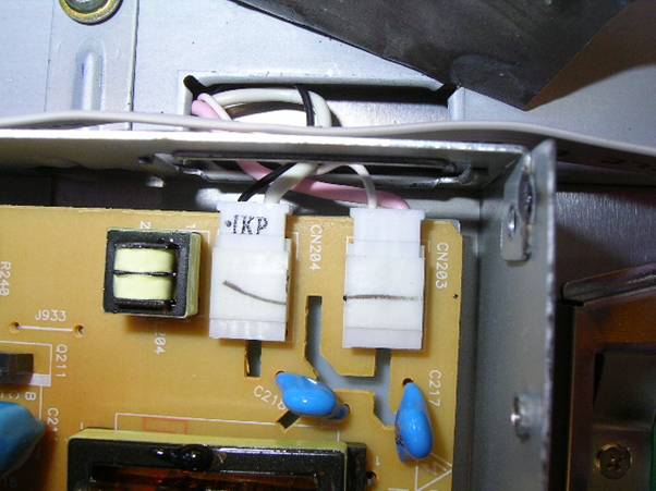
They should be the same as this, but if yours aren’t then keep a note of YOURS.
I am not sure if AOC changed colour coding at any point. We don’t want them the wrong way around.
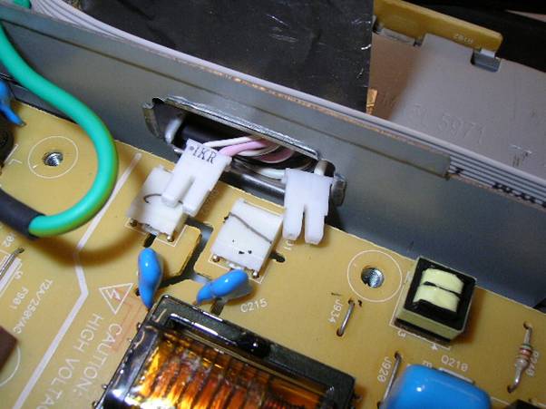
They pull out easy with a pair of pliers on the plastic edge. Make sure they are clear of the board, so you can get the board out.
To remove the board from its holding, you will need to remove the screws that are around the board. I recall there to be 6 such screws.
By pulling ribbon back, you can remove the board to work on the underneath.
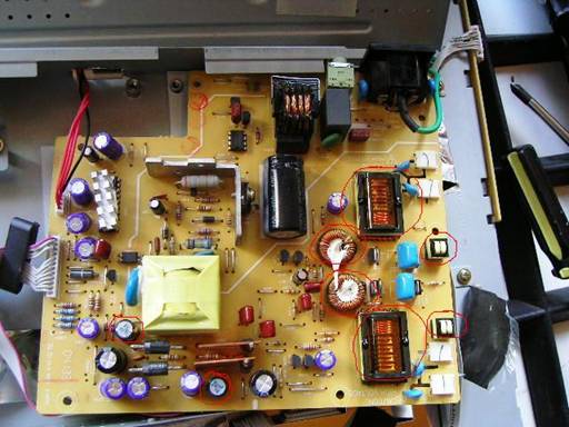
The red rings on the picture above show the transformers and inductors that can get dry joints.
Usually it is just the one coil, but I have seen some bad dry joints on all the coils before today. I usually go overkill and do them all. They are vibrating, so are more prone to bad joints. The joint is quite often the only thing securing them too.
You should be able to spot which one is the true bad joint. It will look rather dry and pitted.
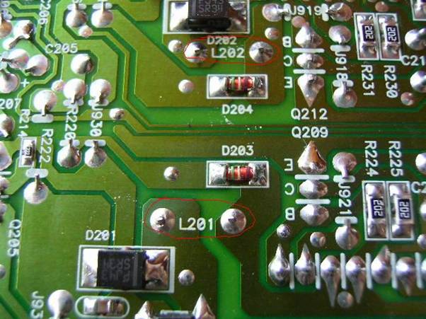
I advise you to de-solder the joint completely before applying new solder. Applying new over old is a bad practice. You really must get a solder sucker, if you don’t have one already. You will see one in a shot here. It is pointing to the true bad joint. I usually do all the coils that are ringed on the shot. You can just go straight for the joint and save time. I usually do any others whilst the thing is in bits.
Be careful not to let solder spill and join adjoining joints. You could expect a bang if you do!!!
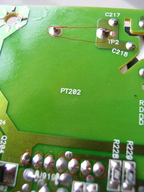
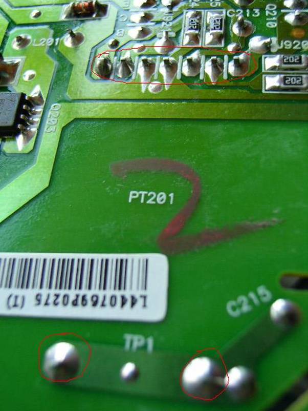
These ones are usually the better joints but I do ‘em anyway.
These ones are the small ones.
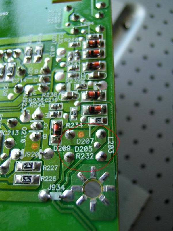
These are important.

As you can see above, the solder sucker is pointing at a very bad joint.
Once you have done these, you are ready to put it back together. Make sure, first of all, that there are no loose bits of solder knocking around on the board.
When you put the board back together, make sure you screw the board back down to the base and put the side connectors back in THE RIGHT WAY!!! See your notes or my pictures, if they were the same.
Put the cover back over the board ONLY when you are sure that everything is in correctly and no solder parts are floating around.
Put the three screws back in on the top plate and re-cover the edges with sticky foil.
The screen will drop back in to the frame easily and you will feel clicks as the lugs click in.
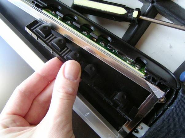
Make sure you put the buttons back in, if you took them out. I have forgotten about this on more than a few occasions!
Screw the plate back in and then you should end up with a lovely repaired monitor.